Your Cart is Empty

Acura RSX DC5 EDM/UKDM DC2 rear fog light installation guide
In Europe, vehicles are legally required to have rear fog light installed much like daytime running lights are legally required in Canada. Rear fog light will enhance the visibility of your vehicle to the drivers behind you under adverse weather conditions, i.e. snow, rain, or fog. This guide will show you how to execute an OEM-like install that utilizes an after market OEM style RSX fog light wiring harness in conjunction with an ‘07-’08 Honda Fit combination switch to control the EDM DC2 rear fog light on your Acura RSX.
As with all my recent DIY guides, I try to keep the installation of non-OEM options appear as OEM as possible. With this in mind, the steps involved are meticulous and detailed. If you do not care for OEM-spec installation and just want to get the fog light functional, you can can simply skip the steps and optional parts and just wire the fog light as depicted in the diagram provided below. Please read this entire guide thoroughly before purchasing parts. I wrote this guide for educational purposes to reference the effort involved in this project. Use this guide at your own risk.
EDM/UKDM DC2 rear fog light installation guide
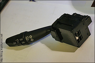
For this install, we’ll be using the ‘07-’08 Honda Fit Sport combination switch with built-in fog light switch based on ClubRSX member gslowr’s original concept. The Honda Fit combination switch will be a direct swap with the RSX combination switch. Utilizing the wiring harness from an after market OEM-style fog lights, which can be purchased on eBay for $50.00, we’ll wire it up so that it functions like OEM-spec. That is, the rear fog light will only turn on if the front head lights are turned on (just like OEM-spec front fog lights). But unlike OEM front fog lights, the rear fog light will not turn off if your high beams are activated. Expect to spend about 2 hours on this modification, wiring and rear bumper cutting included.
Again, for those that are electrically well-versed, you can skip to the circuit diagram at the bottom of this guide and perform the installation at your own pace or method.
This guide assumes that you have OEM Acura fog lights with OEM wiring harness installed.
Legality in the state of California
For the complete legality scoop regarding rear fog lamps usage in the state of California, refer to CVC 24602. The only item that you should be concerned about is clause #5, which states that an amber pilot (indicator) light is lighted when the rear fog light is turned on. Easy to wire up to an LED, or follow the optional rear fog light indicator mod at the bottom of this guide. Obviously if you reside in a different state or country, you should consult your local vehicle code for legality.
Parts needed:
1x ‘07-’08 Honda Fit Sport combination switch, part #: 35255-S5K-F12
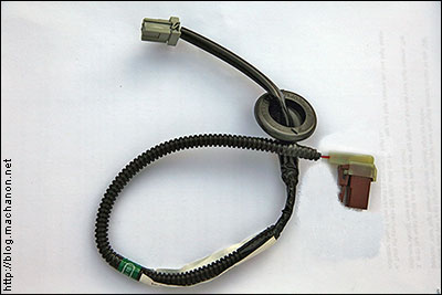
1x Acura RSX license plate light sub-wire, part #: 32113-S6M-A00
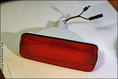
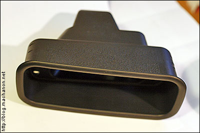
1x EDM spec ‘94-’01 Honda Integra rear fog light, part #: 34450-SV2-G01
1x EDM spec ‘94-’01 Honda Integra rear fog light inner garnish, part #: 71511-ST7-G00
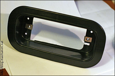
1x EDM spec ‘94-’01 Honda Integra rear fog light outer trim, part #: 71512-ST7-G00
2x Honda 0.50 female pigtails (shown taken from OEM side marker connector).
Part #: 04320-SP0-X10, sold in a bag of 10 pcs.
1x After market OEM-style fog light wiring harness (or 4-pin 30A Bosch style relay with pig tails and 10A blade fuse)
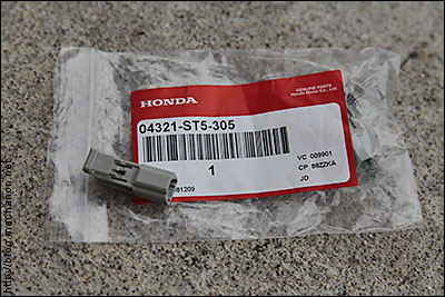
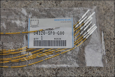
1x 2-pin male connector w/pigtails (part #: 04321-ST5-305, sold in a bag of 5 pcs; male pigtails part #: 04320-SP0-G00, sold in bag of 10 pcs)
1x Rotary tool w/cut-off wheel and grinder/sanding bit
1x 30′ roll of 16 awg wire
1x roll of painter’s masking tape
1x Sharpie marker or ball point pen
1x Wire stripper / cutter
6x Male & female 16 awg quick disconnects (3 of each)
2x Male & female 14-16 awg bullet terminals (1 of each)
1x 14-16 awg quick splice connector
1x roll of wire loom
1x roll of vinyl electrical tape
Templating and cutting your rear bumper
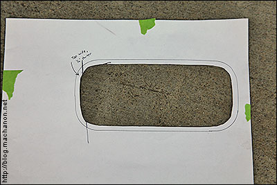
1. To create the template which you’ll use to cut the mounting hole on your rear bumper, we’ll use the outer trim as a reference. This is the piece where the actual rear fog light sits in and is screwed onto. Trace the lip of the trim on a piece of paper. Next, cut 1/4″ inside and along the line you’ve just traced:
2. Take the rear fog light outer trim and test fit it into your template. You may need to make a few changes to ensure a snug fit. Once you’ve determined that the template is good, place it on the section of your rear bumper where you would like to mount the rear fog light and tape the top part of the template onto the rear bumper:
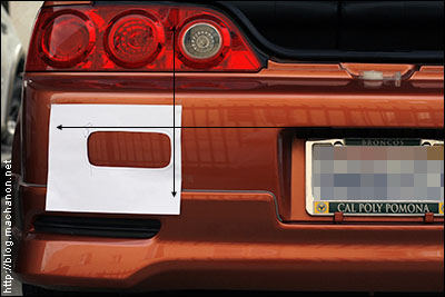
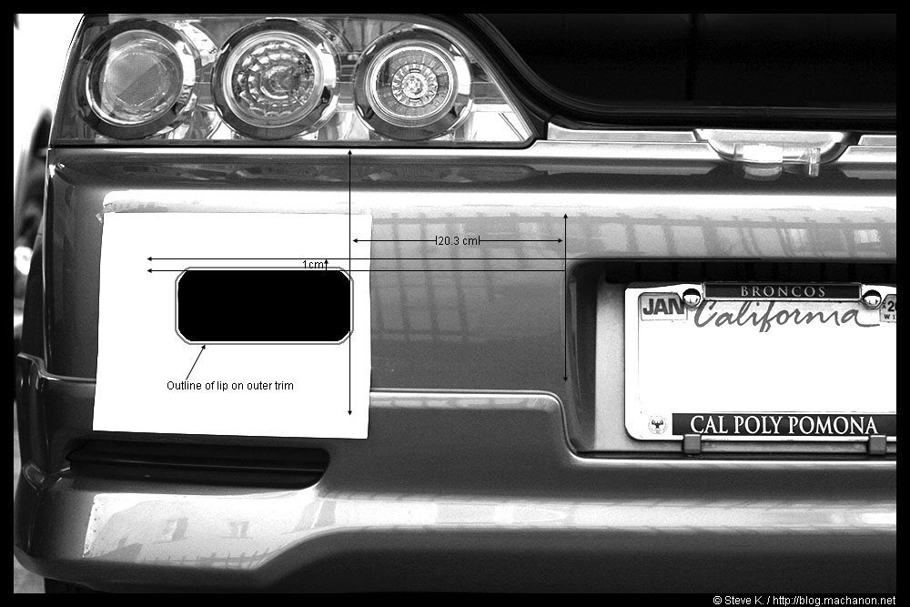
You can use the preceding as a general guide to mount the rear fog light on your ‘05-’06 RSX. The ‘02-’04 RSX models has a different rear bumper so if you’re installing it on an earlier RSX model, you may have to modify the measurements to suit your application.
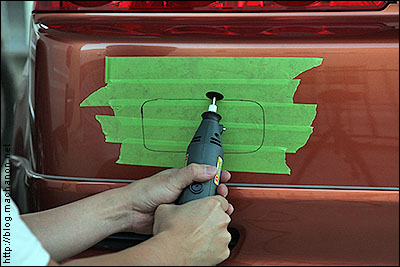
3. Lift up the template (still held onto the rear bumper with tape) and apply a liberal amount of painter’s masking tape over the entire area of the rear bumper where you want to mount the rear fog light. Next, take a pen or a Sharpie and trace over the template cutout onto the taped surface of the rear bumper:
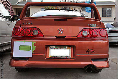
Stand back and examine the template affixed to your rear bumper. If you are satisfied with the location and alignment, it’s ready to begin cutting.
4. It is imperative that you wear safety goggles. DO NOT EVEN ATTEMPT TO CUT IF YOU DO NOT HAVE SAFETY GOGGLES ON! Start by cutting inside the traced line using a Dremel, AllTrade or similar rotary cutting tool equipped with a cut-off disc:
Be ready to use up to 5 or more fiberglass cut-off discs for the cutting (less if you use cut-off discs designed to cut through metal). If you don’t change them when they are overheated or worn, the disc will break and fly at you. It is important that you wear safety goggles to protect your eyes from the flying debris. Another thing to note is the melted plastic flakes flying off the cutting job is also very hot. I recommend wearing a sweater to avoid minute-burns. Once the base pattern is cut, you can switch the bit to a grinding to level out the curved corners:
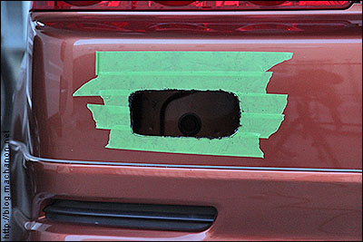
Finish with a sanding disc for a clean presentation. Test fit the outer trim. If the hole is too small, you can use a grinder bit and gradually widen up the hole. REMEMBER: It’s always a good idea to start by cutting a smaller hole – you can always widen it up later if it’s too small. If you cut an oversized hole from the start, it could leave to mounting problems. The key point is to take your time and pace yourself. It took me about 1 hour to perfect the hole.
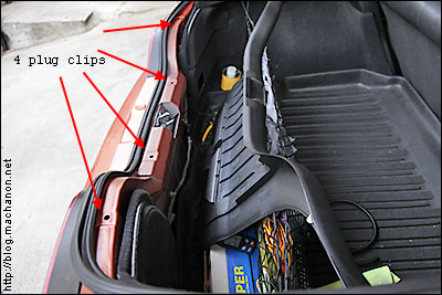
5. Remove the tailgate panel by pulling it upward with slight force. It’s secured onto the rear frame with 4 plug clips:
6. Remove your rear bumper.
Mounting the rear fog light
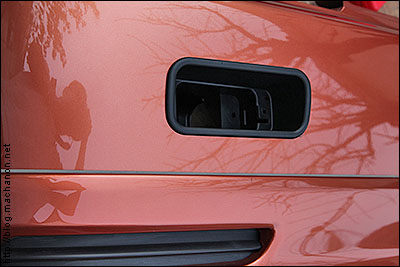
1. Insert the rear fog light outer trim into the hole you’ve just cut:
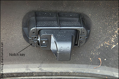
2. Pair up the inner garnish from the inner side of your rear bumper with the rear fog light outer trim you’ve just inserted. Align the 3 notches and key slot, then press the two pieces together until they snap into place to ensure a secure mount. If you’re installing on the left side, the notch key should be on the lower left corner:
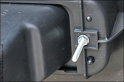
3. Finally, insert the rear fog lamp into the outer trim and secure the lamp into the housing with two screws. Alternatively, you can use two nuts and bolts in place of the screw. You’ll mount the nut from the inside of the rear bumper. This will prevent the rear fog light from being easily removed:
If you are going to use nuts and bolts, remove the two original spring clips from the inner garnish.The bolts used were M5 .7, 50 threads, the nuts used were M5 .8 and the washers used were M5:
For extra security, you may use two nuts per bolt instead of one. The drawback is you’ll have to remove the rear bumper every time you need to change the bulb (unlikely), but the security and peace of mind is well worth the extra effort.
4. This is what it should look like so far with the rear fog light mounted onto the rear bumper:
Flush mount:
Making the connections
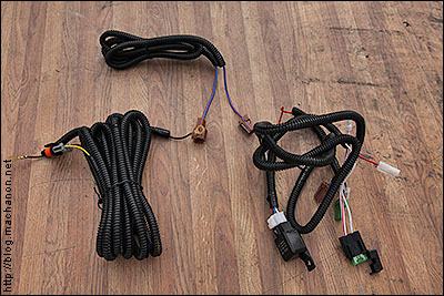
The reason why we’re using an after market OEM-style fog light wiring harness is because it will simplify the installation. Plus everything you need is already part of the harness; no need to purchase additional parts. All you need to do is rearrange a few terminal joints and make a few wire splices to lengthen the power wire. For folks that had to replace OEM fog lights (as I did) with an after market set due to cracked lens caused from road debris, this is a prime opportunity to use the after market fog light wire harness if you happen to save it. For those that do not have an after market wiring harness, follow the circuit diagram below and create your own harness using a few cuts of 16 awg wire, a 10A fuse and a 4-pin Bosch relay (with pigtail).
1. Remove the steering column covering by removing 3 Philips screw on the lower cover and separating the top cover from the bottom cover.
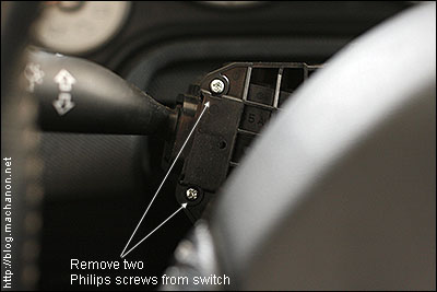
2. Remove two small Philips screws that is securing the combination switch onto the steering column:
3. With gentle force, push the combination switch to the left and out. You may need to pull it out with your hands or push it out with a screw driver.
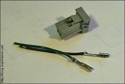
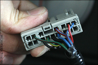
4. Unplug the combination switch 16-pin plug:
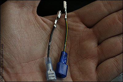
5. Attach a female or male quick disconnect onto each of the two pigtail you’ve acquired. I used one female and one male quick disconnect to distinguish the connections:
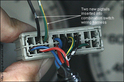
6. Insert the two pigtails into the terminals on the plug as shown. Make sure they are in the correct orientation before insertion. Incorrect orientation can result in a damaged pigtail or plug, or both! If you are not sure, just look at the adjacent pigtail.
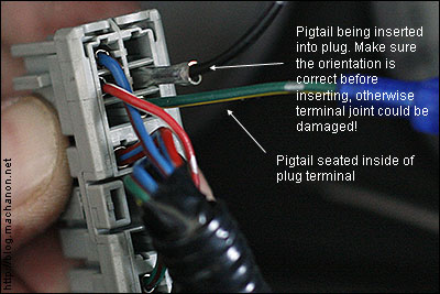
This is what the inserted pigtails will look like, note the correct location:
7. Crimp a quick connect to the positive wire (usually a RED/YEL wire) from the after market wiring harness then connect it to one of the pigtails that was inserted into the 16-pin combination switch plug on step #6. It doesn’t matter which one, but take note of the pigtail you actually make the connection with. This wire is directly connected to pin #86 (or 85) of the fog light relay.
>Take the remaining pigtail (the one that is not connected to the RED/YEL wire on step #7) you’ve inserted and splice it with the BLU/RED wire (pin #4 on the plug). You can use a T-Tap for the splicing.
The pin where the BLU/RED wire is plugged into becomes active when you turn your head lights on. If your Fit fog light switch is in the “ON” position while your head lights are on, the 12v from the BLU/RED wire will trigger the coil in the fog light relay, completing the circuit between pin 30 and pin 87. Alternatively, you can tap this wire into the IGN (ignition) wire to use as a trigger, but to remain OEM-style, this is what we’ll do for the guide.
8. Next, look for a thick WHT/RED wire in the after market fog light harness; it may simply be RED or a WHT wire color depending on the harness you use. This wire should be approximately 12-14 awg thick connected to one blade of a 30a blade fuse while another thinner wire, about 16 awg thick, is connected to the other blade of the same fuse. The end of the thicker WHT/RED wire will terminate in a brown 1-pin female plug. If you have OEM or after market OEM-style fog lights installed, cut off the brown plug and cap off the wire with an end-terminal. Then splice this wire to the OEM fog light wire power wire in your under dash fuse box with a quick splice tap.
Since the wire will be powering a 21w bayonet bulb instead of two 55w H11 bulbs, replace the 30a fuse in the fuse holder with a 10a fuse.
9. Ground the BLK wire from the after market fog light harness.
10. The main wiring connection is complete. You may want to make temporary connections to the rear fog lamp to ensure that the connections you’ve made in the preceding steps work before completing the installation:
To do this, ground the black wire from the rear fog lamp and connect the power wire to the BLU (or BLU/RED) wire from the after market fog light harness – the wire that is directly connected to pin 87 of the fog light relay. You may want to make the temporary connections with a pair of test leads. Note: If using test leads, connect the positive wire first and be extremely careful not to accidentally short out the positive clamp by inadvertently grounding it to any metallic surface! This can damage your test leads, your rear fog light, your combination switch and start a fire. Turn on your head lights, then turn on the fog light control on the Fit switch. If connections are correct, your rear fog lamp should light up. Turn off your head lights while leaving the fog light control on the Fit switch in the “ON” position. The rear fog lamp should turn off.
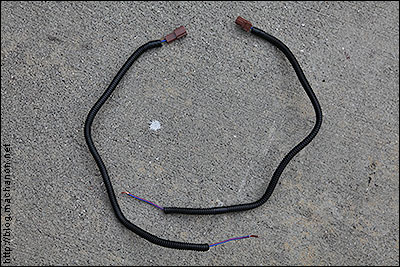
11a. Cut off the 2-pin brown female connector on the license plate sub-wire and crimp the corresponding bullet terminals to the wires (i.e. female bullet terminal to the RED/YEL wire and male bullet terminal to the BLK wire):
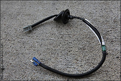
This will plug right into the rear fog light without any modification done to the rear fog light itself.
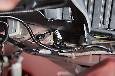
11b. Locate the 28mm hole plug on the left side of the rear firewall. If you want to install the fog light to the right side of the bumper, then use the 28mm hole plug on the right hand side, near the exhaust:
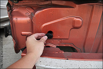
You don’t have to remove it. What you want to do is take a 10mm drill bit and drill through the center of the plug. If the hole is too small, carefully grind the hole to widen it up. You want to make the hole just big enough to snugly fit the rear license plate light sub-wire:
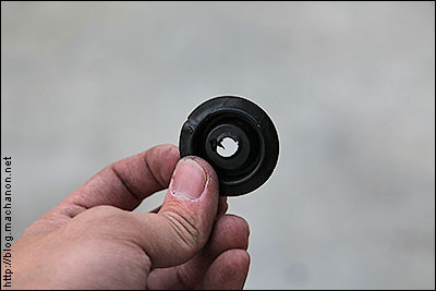
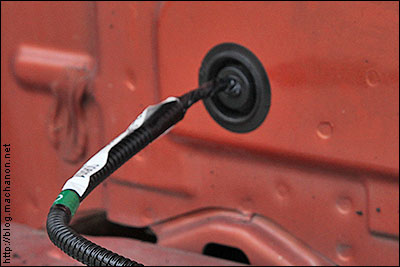
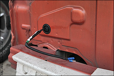
11c. Next, insert the bullet disconnect end of the license plate light sub-wire through the hole drilled from step 11b from the cargo:

Pull the bullet disconnect through the hole drilled onto the 28mm hole plug until the grommet part of it squeezes through. Continue pulling until it will not go further:
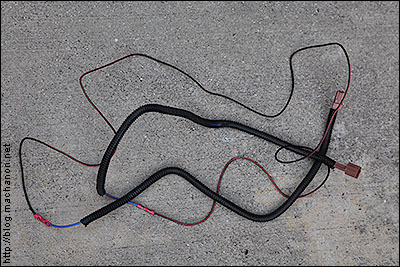
12. Take the BLU (or BLU/RED) fog light power extension wire from the after market fog light harness and cut it in half at the center. Attach approximately 10 feet of 16 awg wire between the cut wires. This will extend the wire to about 15 feet in length. Wrap up the newly extended wire with additional wire loom and tape it up:
13. Take the female brown plug from the wire you’ve extended in step 11 and plug it into the BLU wire that’s trailing from the fog light relay.
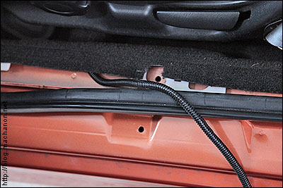
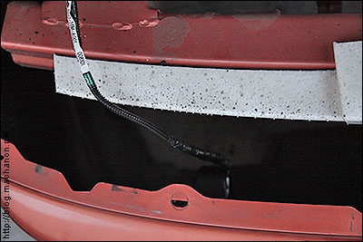
14. Route the extension wire through the driver side door sill,
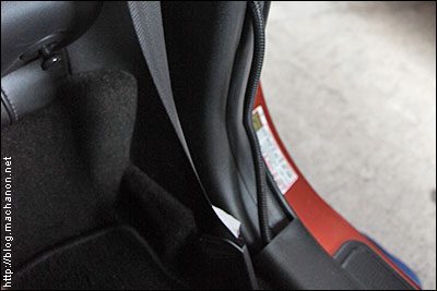
through the driver side rear quarter panel (you may want to remove the speaker grill for easy access to the wire),
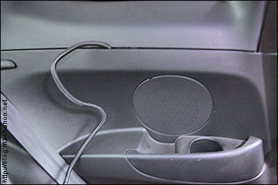
through the driver side rear cargo panel,
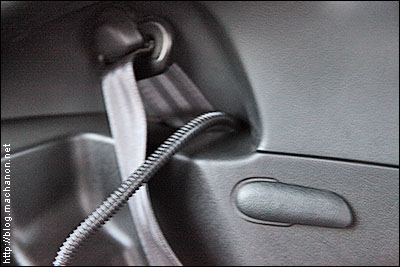
and finally into the tailgate panel which you’ve removed earlier.
15. This step is entirely optional. You can splice the BLU (or BLU/RED) extension wire with the RED/YEL wire from the license plate light sub-wire for a direct connection, and ground the BLK wire to any metallics surface. Or to keep it OEM-style, cut off the brown plug at the end of the BLU (or BLU/RED) extension wire. Attach a male 0.50 Honda pigtail (part #: 04320-SP0-G00) onto the cut wire. Take another male pigtail and splice approximately 1.5 feet of 16 awg wire to the end of it (this will be the ground wire).
Take a 2-pin male connector (part #: 04321-ST5-305) and align it with the license plate sub-wire 2-pin female connector and note the position of the RED/YEL and BLK wire (i.e. BLU aligns with RED/YEL and BLK with BLK):
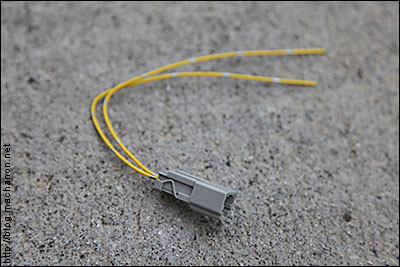
Insert the pigtails into the male 2-pin connector accordingly:
then plug the license plate light sub-wire into this newly created 2-pin male plug:
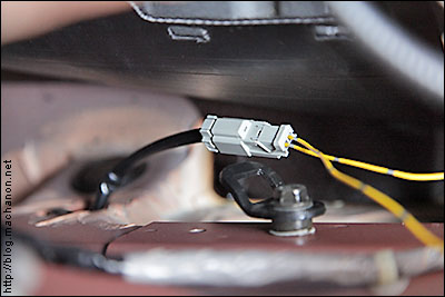
Connect a fork or ring terminal connect to the end of the BLK wire then ground it to the factory tailgate ground bolt. Wrap the wires in wire loom and tape the looms with black vinyl electrical tape for a clean OEM appearance:
This is how the completed connection should look like at the rear bumper end. Clean and OEM looking. Test the rear fog light one last time, then make the final connections and reinstall your rear bumper:
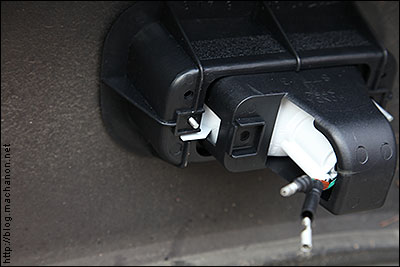
Plug the bullet terminals from the rear fog light into the corresponding bullet terminals on the license plate light sub-wire, then cover the connectors with a 3 inch piece of wire loom. Tape up the wire loom securely with vinyl electrical tape:
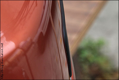
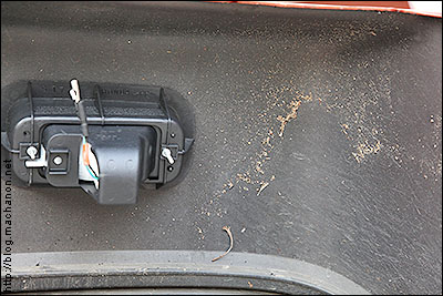
This step is important because the rear wheels kick up a lot of gunk from the road and tosses it into the cavity of the rear bumper. If it rains, water picked up from the rear wheels can cause an unwanted short if the wires are not weatherproofed thoroughly. This is another reason why all electrical connections need to be fused and relayed.
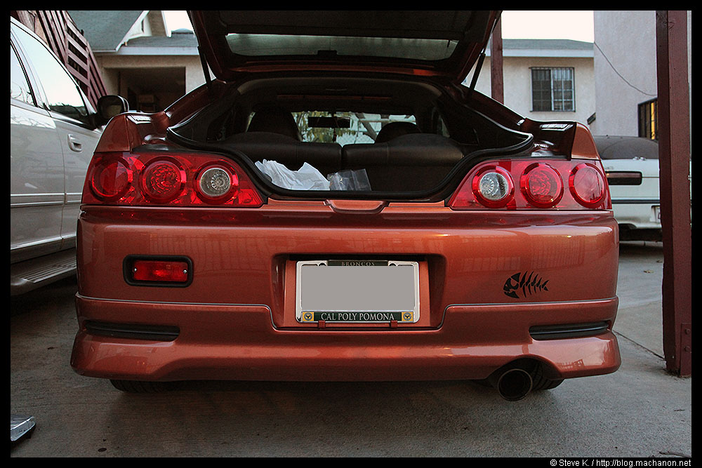
To give you an idea of how far dirt and gunk gets kicked up, look at the debris stuck onto the inside of the rear bumper and how close the rear fog light is to the debris:
Rear bumper reinstalled with rear fog light mounted and wired, ready for use:
Completed install
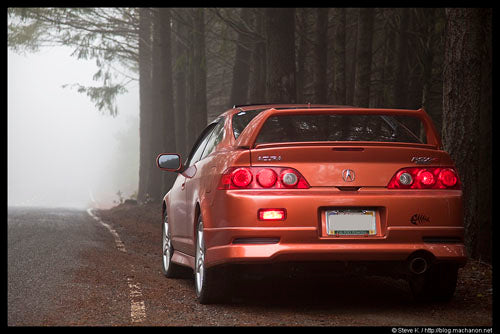
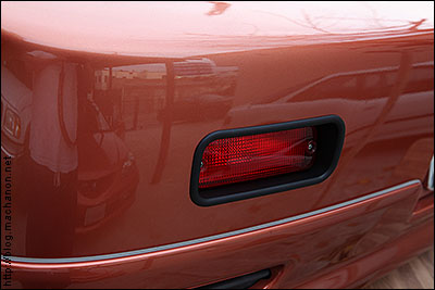
Some shots of the rear fog light installed and operating:
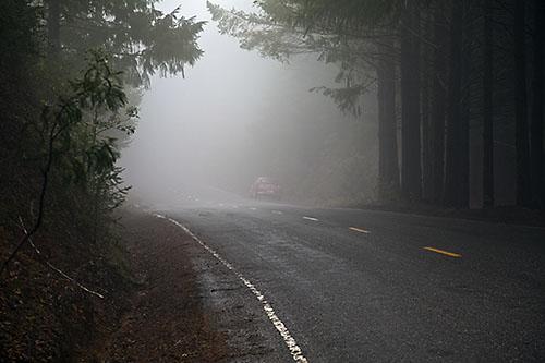
Are rear fog lights effective?
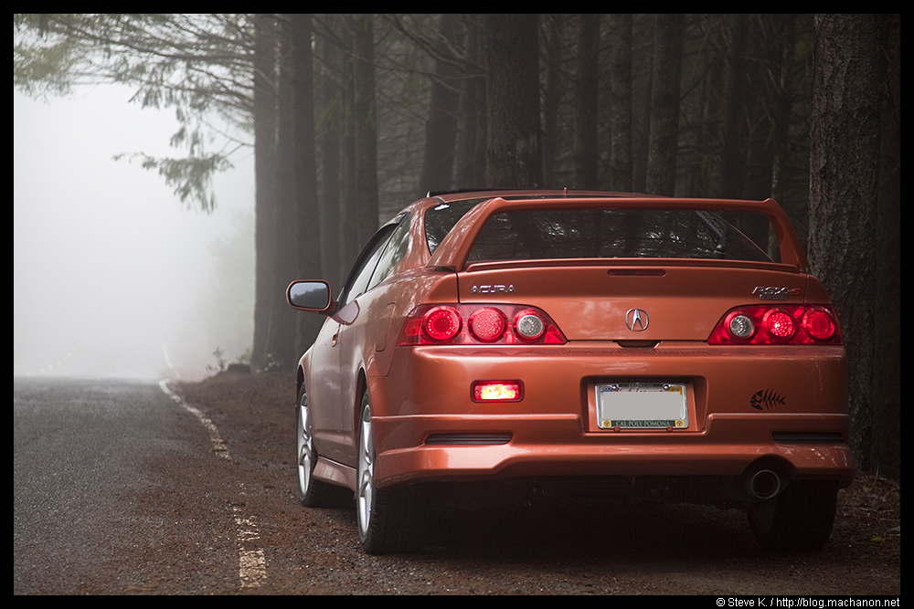
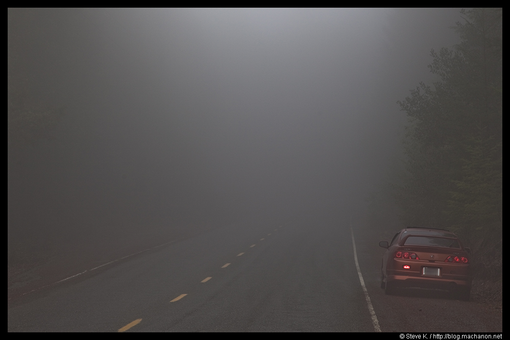
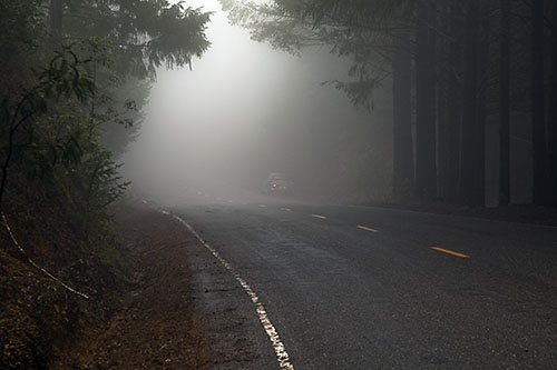
Yes, especially when you drive in an area with a lot of fog, rain or snow. Below are several pictures of my RSX on Briceland Thorn Road in Garberville/Shelter Cove/Whitethorn, CA; ~150 feet away with thick fog (according to my Garmin hand-held GPS).
Here’s a photo taken with just the parking lights on:
Here’s another photo with the rear fog light on:
Since I drive through the desert and through the coastal fogs from central to northern California quite often, this is a highly functional and beneficial mod.
Original DIY by http://www.diymyhonda.com/rsx/edmukdm-dc2-rear-fog-light-installation-guide/